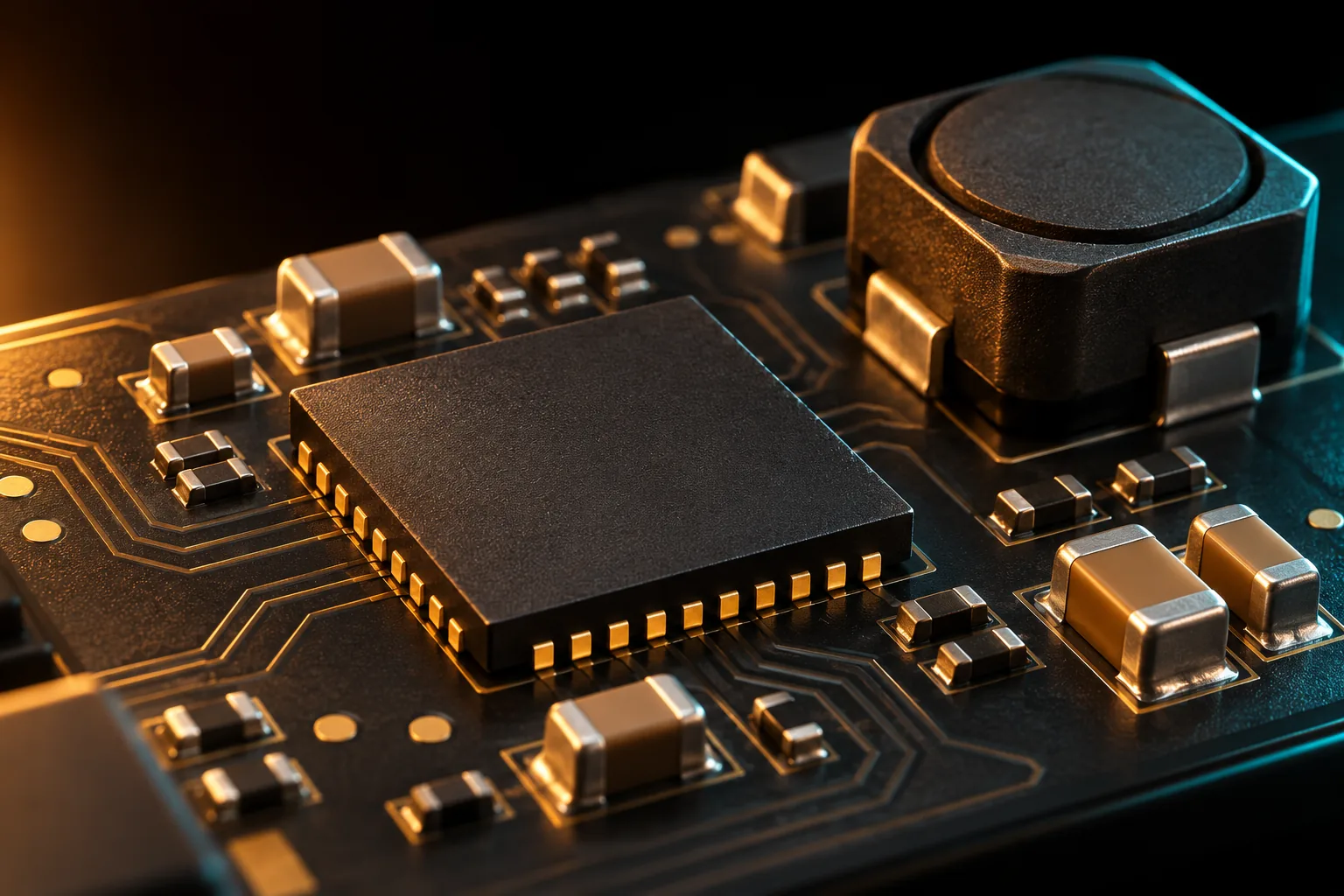
Designed around the demands of 48V industrial buses, electric two-wheelers and energy systems. Wide-input control and integrated protection support resilient power-stage design.
Local chip functionality remains available without an internet connection. Cloud connectivity expands services rather than replacing the local operating path.
INDUSTRIAL POWER
FVX-PM4801Q
● OFFLINE / LOCAL OPERATION
Full power-management functionality. No network required.
Power conversion & regulation
Local protection & recovery
Independent supporting power rails
↗ CONNECTED / SERVICE EXTENSION
Optional supervisory telemetry and maintenance. Connectivity is not required for local power management.
Product functionality statement supplied by FuuVeXia. Core offline language lists, deployed model packs, storage configuration and characterized translation latency are defined in controlled product / integration releases. Public diagrams retain conceptual functional pins pending the formal datasheet.
FVX-PM4801Q
Designed into your system.
Review the operating envelope, interfaces and evaluation conditions as part of a complete design-in process.
Input range9–80 V DC
Process0.18 μm HV BCD
PackageQFN-32 · 5 × 5 mm
DESIGNED FOR INTEGRATION
Wide-input synchronous buck-boost controller
01
Design for variable input
A wide operating window supports system design around changing source voltage. Validate transient limits against the final electrical specification.
02
Protect the power stage
Overcurrent, overtemperature and undervoltage functions provide a foundation for system-level fault management.
03
Evaluate the complete circuit
MOSFET selection, inductor losses, board copper and operating point determine efficiency and thermal performance.
SYSTEM VIEW
Architecture at a glance.
01
INPUT / 48V BUS
→
02
CONTROL & FEEDBACK
→
03
EXTERNAL POWER STAGE
→
04
REGULATED OUTPUT
Previous functional flow · retained
01INPUT / 48V BUS
→
02CONTROL & FEEDBACK
→
03EXTERNAL POWER STAGE
→
04REGULATED OUTPUT
Functional concept only. Not a circuit schematic or verified die floorplan.
TECHNICAL OVERVIEW
Start with the essentials.
Preliminary specifications supplied for this portfolio. Request the controlled datasheet and evaluation conditions before design-in.
¹ Measurement conditions and characterization reports pending confirmation. ² Detailed configuration or rating definition must be confirmed. Availability and qualification are subject to engineering review.
FVX-PM4801Q specifications
Input range
9–80 V DC
Process
0.18 μm HV BCD
Package
QFN-32 · 5 × 5 mm
Peak efficiency¹
96.8%
Protection
OCP / OTP / UVLO
Temperature²
−40°C to +125°C
APPLICATION FOCUS
Built around your system.
01
Industrial power
Discuss operating conditions, interfaces and validation requirements with the engineering team.
02
Energy storage
Discuss operating conditions, interfaces and validation requirements with the engineering team.
03
Electric two-wheelers
Discuss operating conditions, interfaces and validation requirements with the engineering team.
ENGINEERING IN CONTEXT
A closer look.
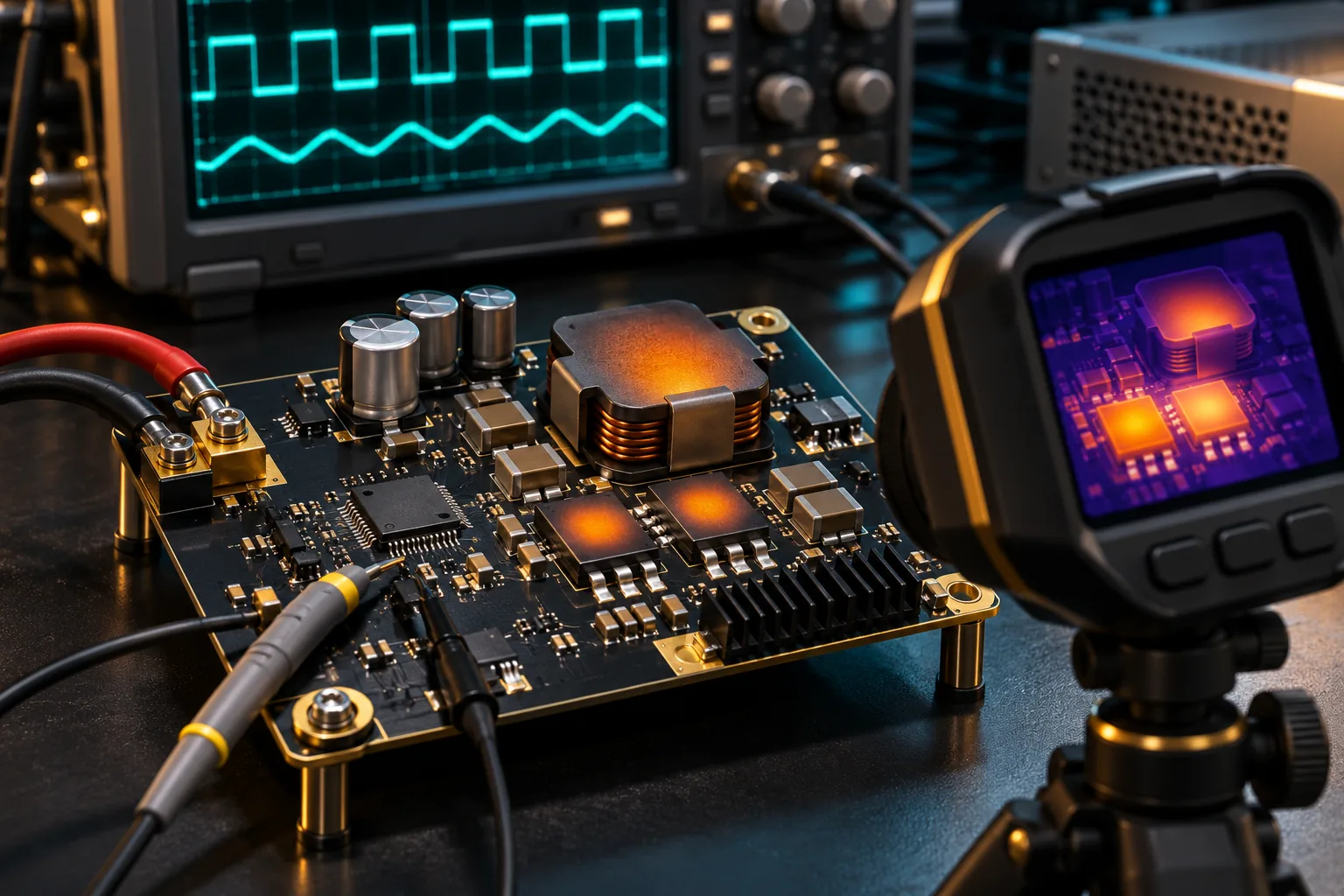
Thermal design evaluation
Original concept illustration · not evidence of owned facilities or actual products
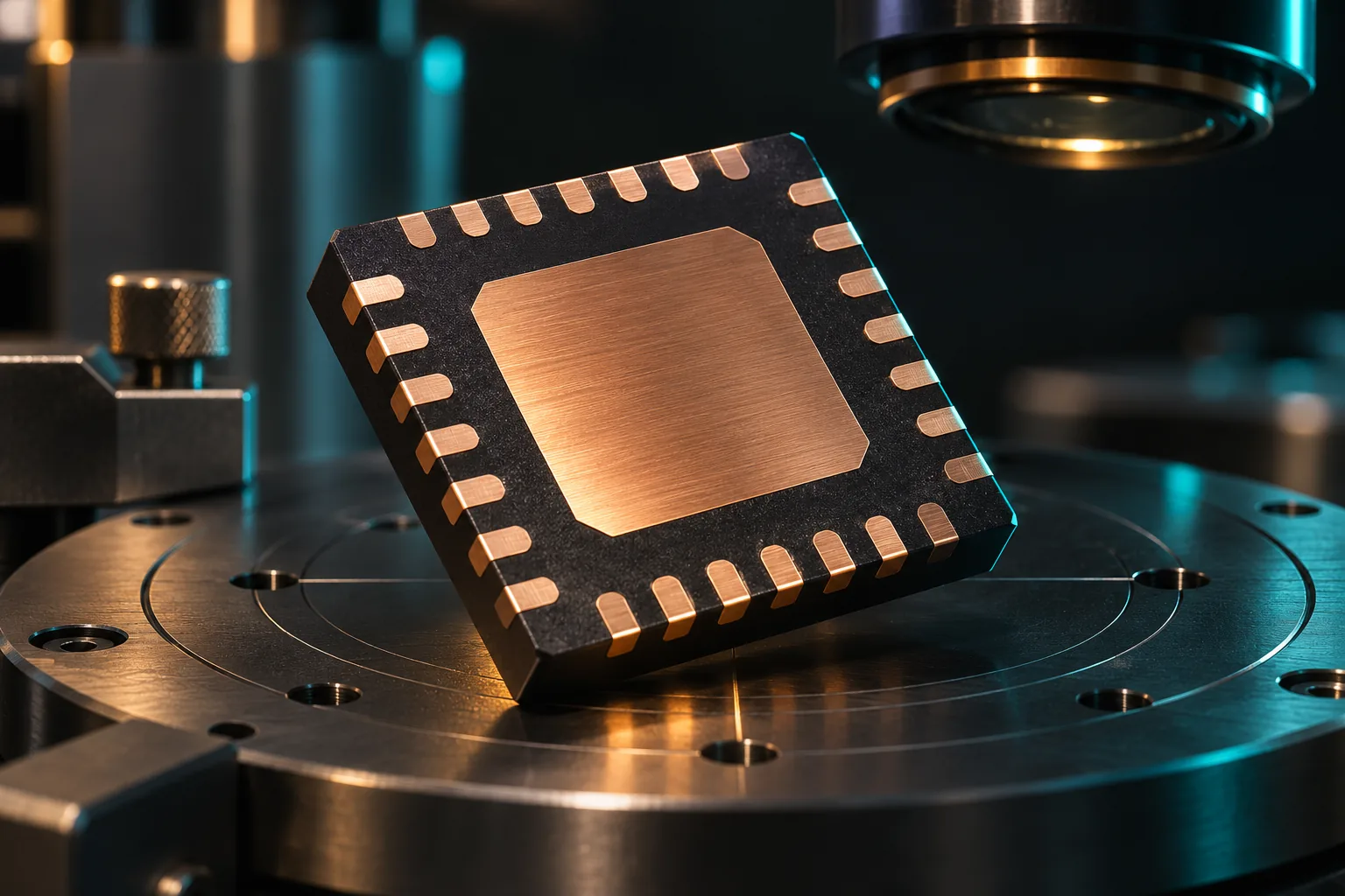
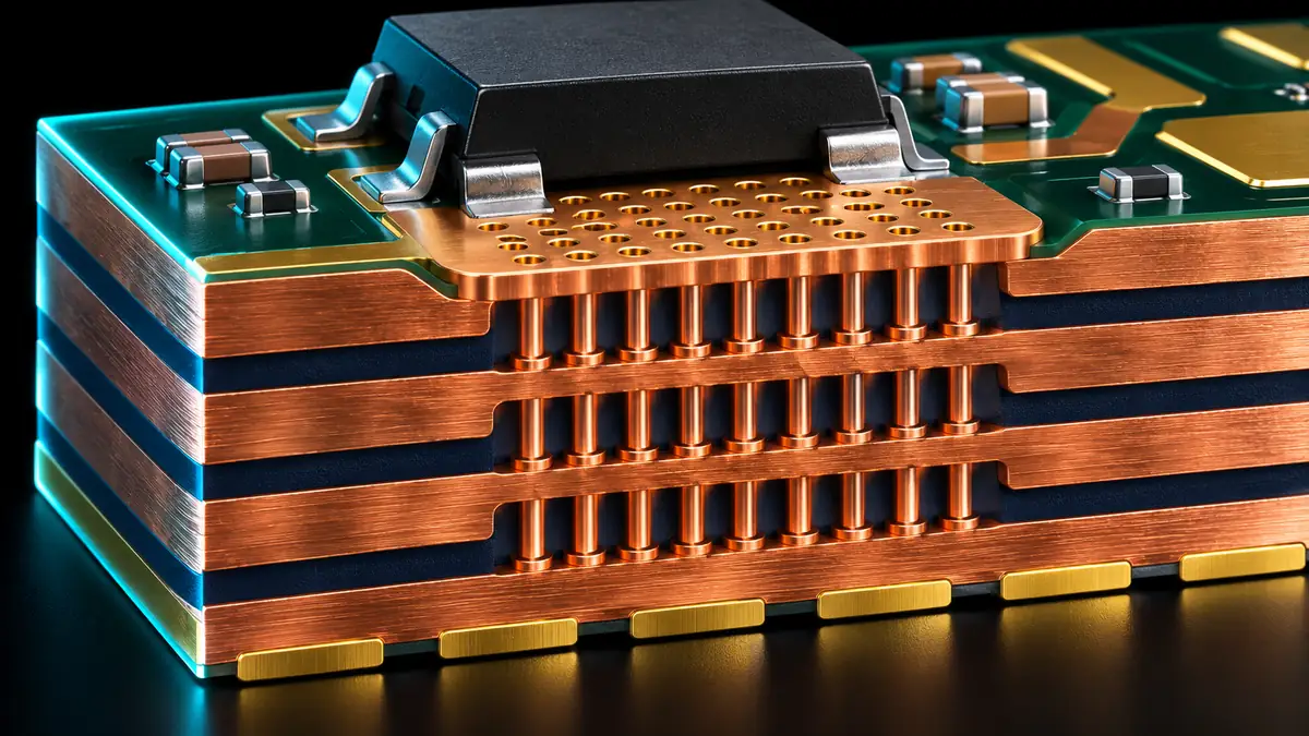
Package integration
Original concept illustration · not evidence of owned facilities or actual products
Follow the energy from the source to the load. The following design dossier expands component selection, board layout, thermal planning and a reproducible evaluation workflow.
ENGINEERING IN FOCUS
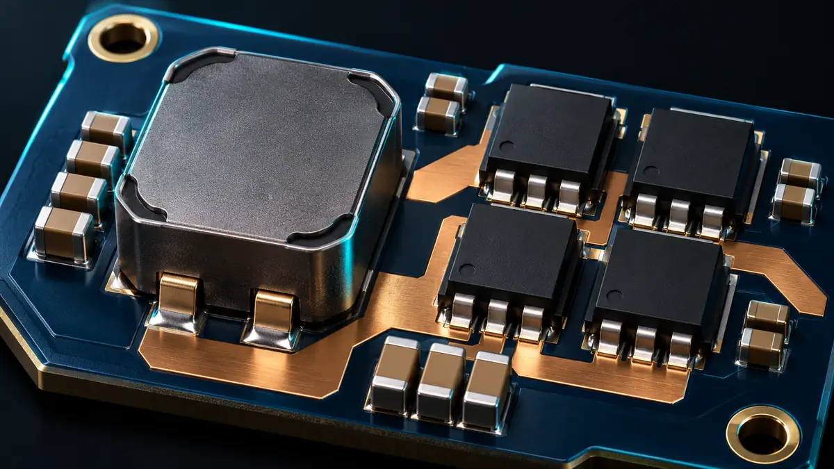
Magnetics and switching devices
Evaluate inductor saturation, winding loss and MOSFET switching behavior as one power-stage problem.
Original concept illustration · not a photograph of the released product or owned facilitiesENGINEERING IN FOCUS
Characterize the load envelope
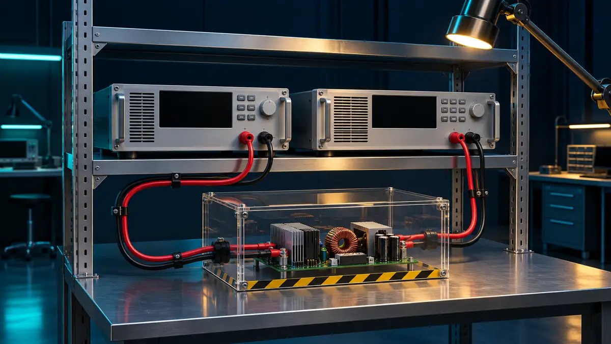
An electronic load helps exercise steady-state, startup and dynamic conditions across the operating window.
Original concept illustration · not a photograph of the released product or owned facilities
SYSTEM RESPONSIBILITIES
Define every boundary.
Functional design perspective; external circuits and interfaces require confirmation against the controlled specification.
01
Source & protection
Input source → protection → local decoupling
02
Energy conversion
Controller + external switches + inductor
03
Regulation & load
Output network → load → sensed feedback
BOARD & SYSTEM INTEGRATION
From part selection to system design.
01
Select an inductor for the entire envelope
Review peak current, saturation behavior, winding resistance and core loss at the selected switching conditions. A room-temperature current rating alone does not establish margin at a hot operating point. The appropriate inductance depends on ripple targets, transient requirements and the final control architecture.
02
Treat layout as part of the control loop
Keep high-current switching paths compact and separate sensitive feedback from noisy switching nodes. Route current-sense connections as deliberate measurement paths. The final pin map and reference layout must come from the controlled product documentation; the conceptual illustrations here are not PCB manufacturing files.
03
Design protection as a coordinated response
Input undervoltage, current limiting and thermal shutdown act at different boundaries. Define whether a fault should latch, retry or wait for a host decision. Check that recovery does not repeatedly stress the external MOSFETs, source connector or load. Product-specific thresholds and timing remain subject to the released specification.
External references describe general engineering principles; they do not validate or endorse this FuuVeXia product.
ENGINEERING IN FOCUS
Auxiliary power for electric mobility
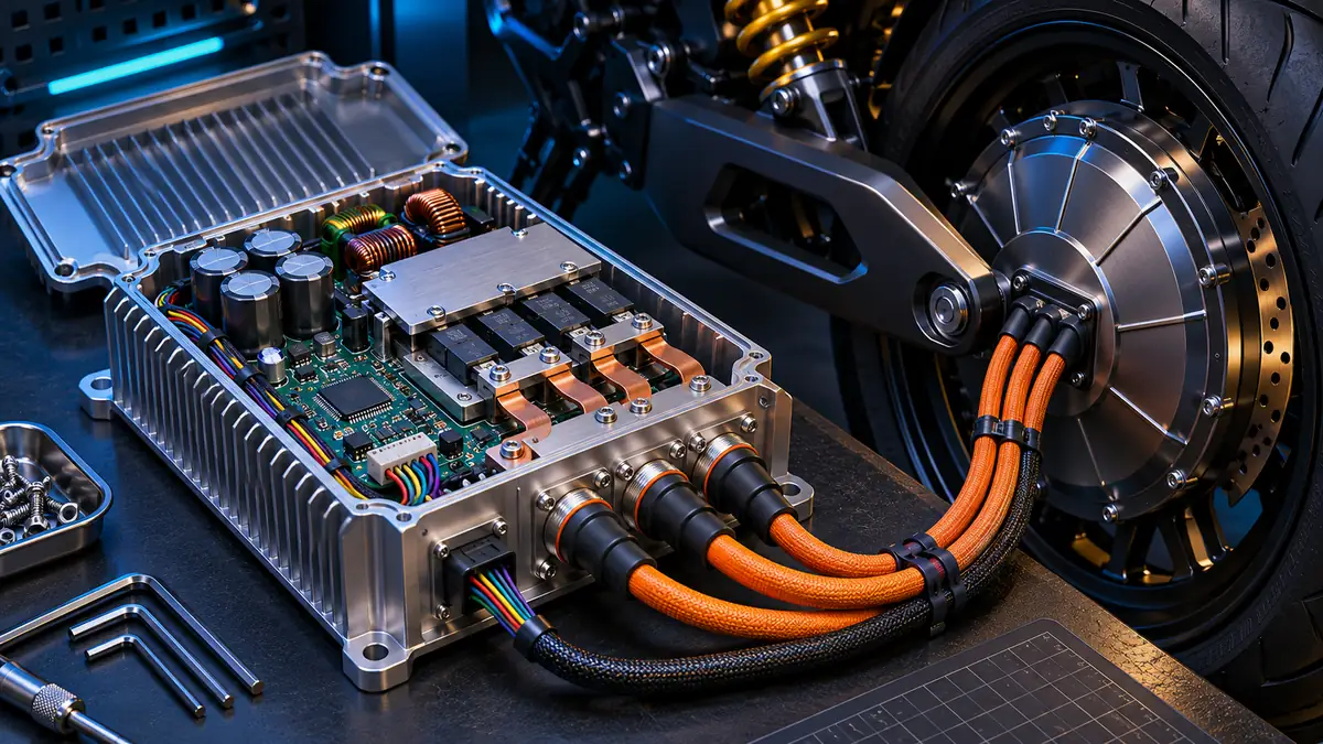
Separate traction power, control rails and always-on electronics before defining the supporting DC–DC stage.
Original concept illustration · not a photograph of the released product or owned facilitiesENGINEERING IN FOCUS
Engineer the board as a component
Copper geometry and thermal paths influence losses, temperature rise and repeatability.
Original concept illustration · not a photograph of the released product or owned facilities
VERIFICATION PLANNING
A test plan you can discuss.
Evaluation
Define the conditions
Record the evidence
Input sweep
Minimum, nominal and maximum supply
Regulation, current and protection behavior
Load sweep
No-load through intended full load
Efficiency, ripple and temperatures
Transient response
Defined load step and slew rate
Undershoot, overshoot and settling
Start / stop
Slow ramp, hot plug and brownout
Inrush, sequence and restart state
Fault recovery
Controlled overload and short circuit
Peak stress, retry and recovery
Thermal margin
Final enclosure and representative airflow
Hot spots and steady-state rise
Planning matrix, not completed test results. Acceptance limits must be agreed against the current device revision and application requirements.
ENGINEERING INTERPRETATION
Loss budgeting before layout
For an illustrative 24 W output at an assumed 92% efficiency, input power is 26.09 W and total conversion loss is 2.09 W. This is a calculation, not measured PM4801Q performance. Allocate those losses across the switching devices, magnetics and other components before evaluating temperatures.
24 W ÷ 0.92 = 26.09 W26.09 W − 24 W = 2.09 WIllustrative system reasoning · not a measured product benchmark
ENGINEERING QUESTIONS
Before you commit the design.
Does the controller define the maximum output current?+
No. The current capability of a design depends on the external power stage, magnetic components, sensing limits, thermal environment and the controller’s final specifications.
Is the 100 V transient figure a continuous input rating?+
No. The supplied 100 V figure is an unverified transient target. A usable surge rating also requires waveform, duration, impedance and repetition conditions.
Can it replace another part without changing the PCB?+
A drop-in claim needs a named comparison part and a complete pin, electrical, control-loop and layout review. No universal pin-compatible replacement is asserted here.
Does −40°C to +125°C establish automotive qualification?+
A temperature target is not a qualification report. Confirm the applicable grade, test conditions and completed qualification evidence for the intended application.
FVX-PM4801Q / NEXT STEPS
Bring the right inputs to the review.
Share your operating conditions, host platform, enclosure constraints and intended qualification requirements. Include the evidence and documentation your procurement team needs.